|
from AGM to LiFePO4 The auxiliary battery in our Sprinter failed for the second time (first covered under warranty) and rather than replacing it with another AGM battery, I decided to go with a LiFePO4 battery. The 92Ah AGM auxiliary battery is separate from the main starter battery and powers the rear cabin lights, two Maxxair fans, rear USB ports, and 12V sockets. We also used it for a 12V refrigerator and a 1kWh power station through the 12V sockets which aren't very good and particularly annoying when it randomly pops out. I selected the Eco Worthy 150Ah LiFePO4 battery, which closely matched the dimensions of the factory Mercedes AGM battery. After some research, the conversion presented two primary challenges: (1) the Sprinter’s charging system is designed for AGM chemistry and (2) when the ignition is on, the auxiliary battery ties directly to the starter battery, creating compatibility issues when mixing chemistries. I reverse engineered the electrical system and came up with the shematic shown in figure 1. 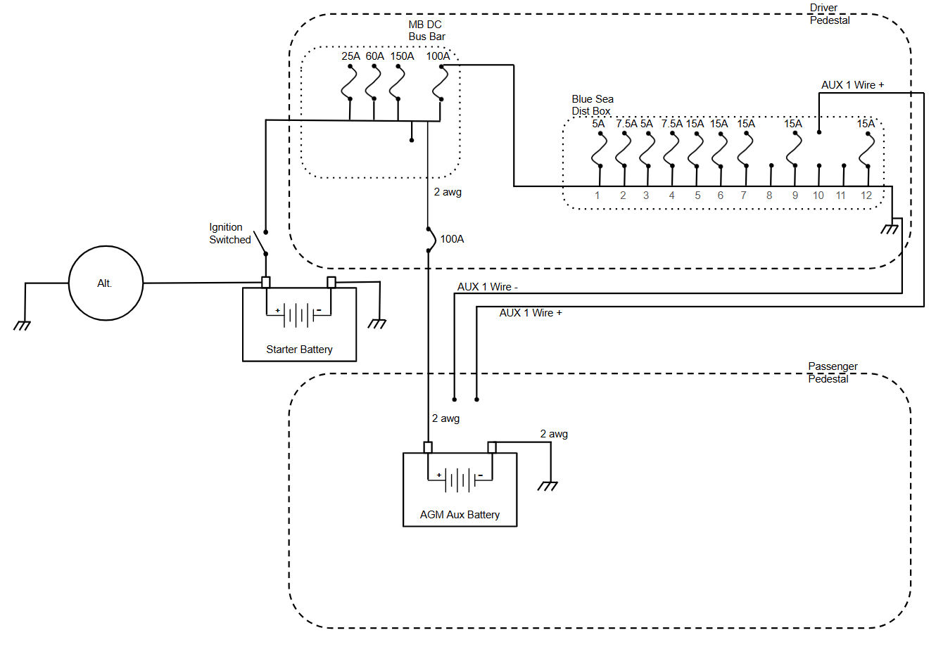 Figure 1. Original AGM based Electrical System With the help of Tomm Aldridge, we designed a system that isolates the new LiFePO4 battery and the auxiliary loads from the main starter battery. The installation added a Victron DC-DC charger that supports LiFePO4 charging, an AC-DC charger, a 2000W inverter, and two dedicated fused circuits: a 15A line for the 12V refrigerator and a 30A XT60 (10 AWG) connector for charging the 1kWh power station or powering other accessories. The design prioritized minimizing cutting and splicing by reusing factory wiring wherever possible. For new wiring, three 6 AWG THHN conductors were added in red (positive) and blue (negative). 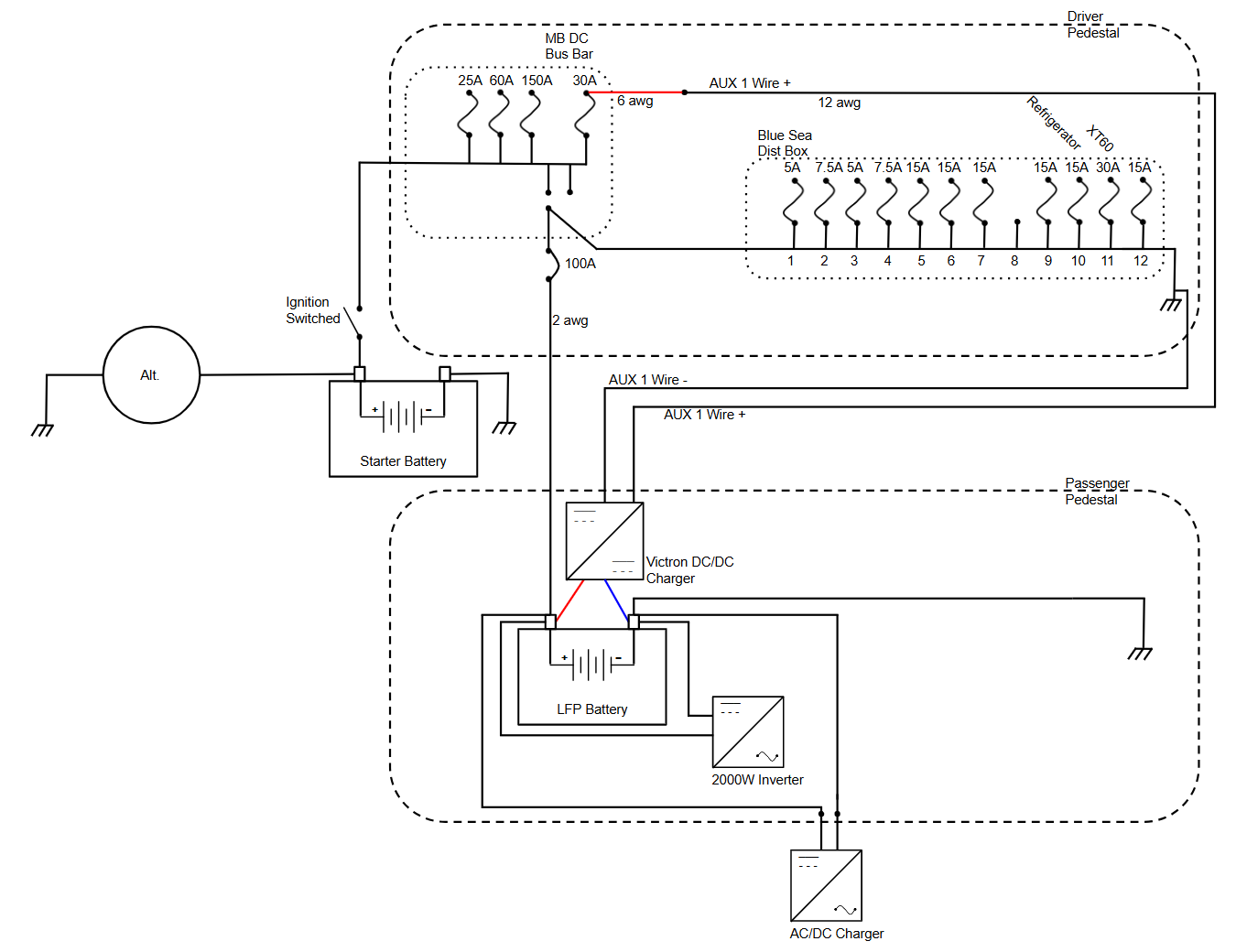 Figure 2. New LiFePO4 based Electrical System The MB DC Bus Bar was previously connected to the Blue Sea Distribution Box. The “AUX 1” 12 AWG wire in the passenger seat pedestal had been connected to an unfused #10 line in the Blue Sea distribution box. That connection was repurposed to feed the ignition-switched 12V line from the starter battery into the Victron 18A DC-DC charger, configured for LiFePO4. I did not go with the 30A or 50A Victron charger due to the use of 12 awg wire. A 30A fuse was used due to fact that I could not find a 25A AMI/MIDI fuse. According to an automotive wiring gauge table Tomm sent me, 30A requires 10 awg above 15' and I'm assuming the AUX 1 wire between the driver and passenger pedestals just a couple of feet apart is less than 15 feet. The LFP battery connects to the DC-DC charger, and the inverter is wired directly to the battery. The 120V AC to DC charger on the bottom of Figure 2 connects with an Anderson Power Connector. After putting everything together, I tested the different sub system voltages and verified everything worked.
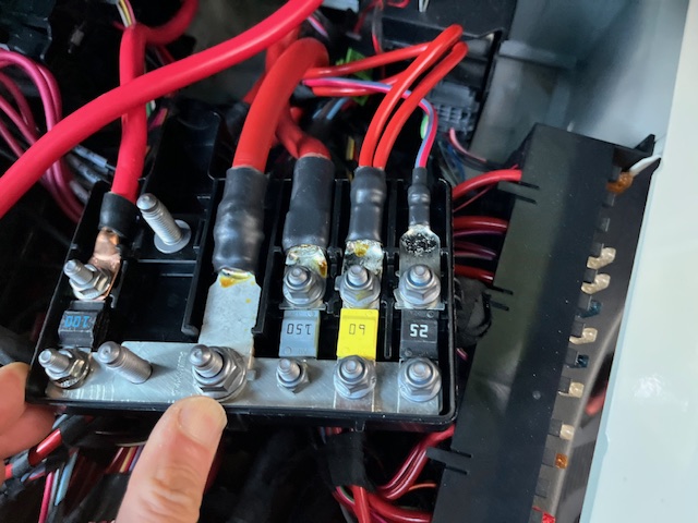
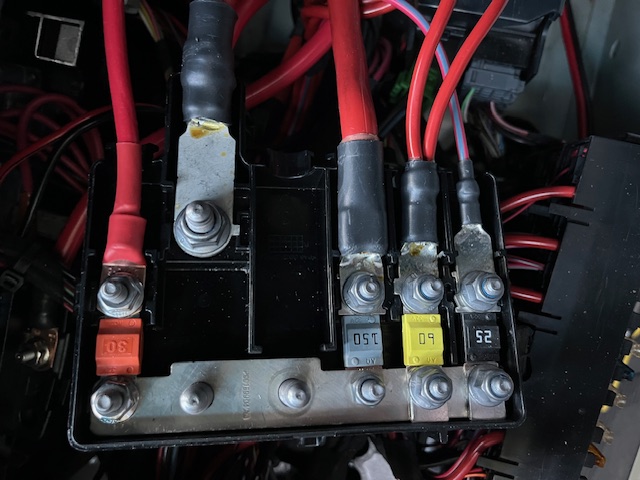
The MB DC Bus Bar connects to the switched ignition. The AGM positive terminal is connected to the bus bar.
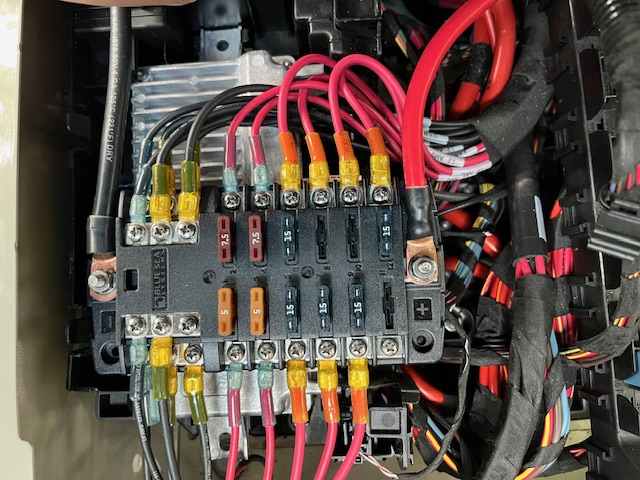
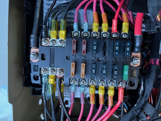
The positive terminal to the auxiliary battery on the MB DC bus bar repurposed to connect the LFP battery positive terminal to the Blue Sea Distribution box via the 100A breaker. Added a 15A fuse to #10 for the 12V refrigerator and a 30A fuse for the XT60 connector. |